

It will only correctly plot them if edges are in a separate layer from faces (as show in image below). Meshlab has problems representing files with both edge and face elements. It will only export vertex and faces to file. ply files with edge elements, but will not save then to ply file format. This is how previous example is rastered by meshlabĪs I said, meshlab supports edge element just partially, so it has some problems: Chances are that your 3D application already has this. Fortunately there's a solution known as polygon reduction (also known as mesh decimation). Some tools like ZBrush can quickly create a high polycount, so it's easy to run into this limit.
#Using meshlab how to
plyĬomment object: 4 edges with color per vertex The maximum amount of polygons our printers can work with is 1 million. How to Create an STL file from a 3D scan point cloud file in MeshLab. If you look back to one of the largest 3D printing projects Ive tacked using desktop machines, the Mario Kart Trophy, youll see its not the first time Ive.
#Using meshlab free
MeshLab is free and open-source software, subject to the requirements of the GNU General Public.
#Using meshlab software
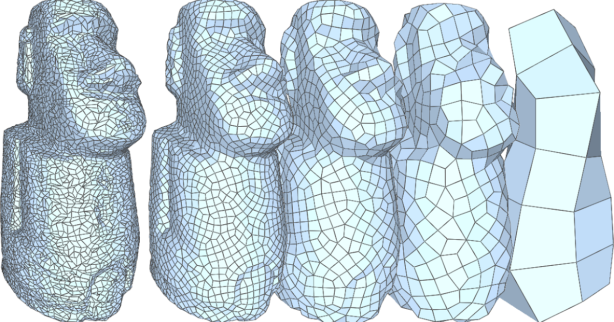
ply file with two vertex and one edge element plyĪnd this is a more complex example, with color per vertex and 4 lines in the corners of a cube. MeshLab is a 3D mesh processing software system that is oriented to the management and processing of unstructured large meshes and provides a set of tools for editing, cleaning, healing, inspecting, rendering, and converting these kinds of meshes. ply file format also allows the definition of segments using the edge which are only partially supported by Meshlab. Remember that, whenever you use MeshLab in a official/commercial project or in. I tried to replicate the issue on a different point cloud, and produced a very similar result, albeit with a mesh that represents only about 1/5th of the point cloud this time:įresh attempt with a different point cloud.There is a way to add lines to. An oiverview of MeshLab software used for sculpting complex 3D assets. I have no idea why the mesh stopped where it did. You can clearly see the different Bounding Boxes.Īnd here's the mesh on its own. Here's the point cloud I'm starting with: The remaining 3rd of my point cloud didn't seem to be meshed at all, and the Bounding Boxes of the two layers (point cloud and mesh) are radically different, with the mesh cutting off a big chunk of the cloud. MeshLab is a very powerful application that can and should be used as a standalone application when working with mesh type files (see Why use MeshLab). > Surface Reconstruction: Screen Poisson), which produced a good result for about 2/3rds of my point cloud. To reset your part view Select View and then Select Reset Trackball. You can also select the X,Y,Z Origin button to help with your origin. Left Click your mouse and pan around your part to ensure everything looks correct.

I then used the Screen Poisson filter to create a mesh (Filters > Remeshing. Procedure: First hit File and Import your Mesh file (STL). VisualSFM is photogrammetric software, using the principles of Structure from Motion (SfM) to extract 3-D information from a set of overlapping images. > Compute Normals.), which seems to work. Chances are high that the object will be surrounded by. I've assigned normals (Filters > Normals. Using Meshlab to Clean and Assemble Laser Scan Data Step 1: Cleaning Scan Data.

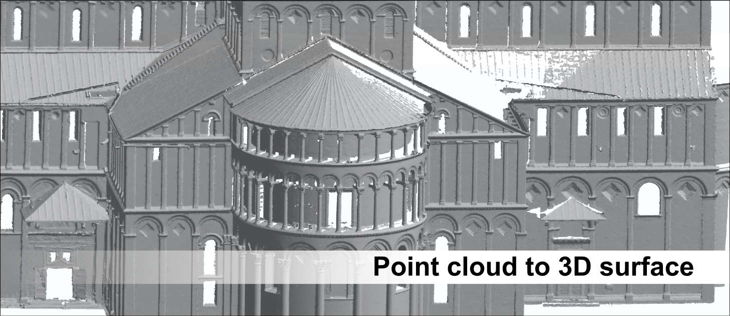
I'm able to clean up and subsample the raw point cloud in CloudCompare, and have been trying to create a mesh in Meshlab. Help! I'm trying to create a mesh from a point cloud (created via on-site laser-scanning), and Meshlab is giving me difficulty.


 0 kommentar(er)
